
RiverBin PROJECT
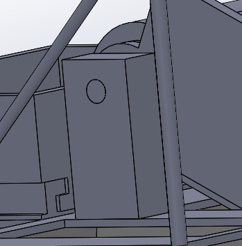
Support Beams
SDG 14:
Conserve and sustainably use the oceans, seas and marine resources for sustainable development
Pollution in marine ecosystems not only affect global oceans but also local waterways such as rivers, ponds, and local ports. Despite growing awareness and cleanup efforts internationally, pollution levels still remain high with much of the waste originating from local waterways before entering the ocean. This waste can harm marine life and human health as it breaks down into microplastics.
To address this issue and support the United Nations Sustainable Development Goal 14: Life Below Water, this project aims to develop an affordable and accessible floating rubbish collection robot that local organisations can implement to capture floating waste before it reaches the ocean.
Approaching The Problem
Our group decided to approach the problem systematically. We first focused on understanding the problem so we could properly define the functional requirements of the skimmer robot. Through market research and identifying a target audience, we looked at existing skimmers and how our design could stand out from them.
We then broke the system down into subsystems such as the conveyor belt collection, hull, propulsion, power supply, and control system. Each part was then designed and analysed individually, considering factors like cost, durability in marine environments, and ease of maintenance.
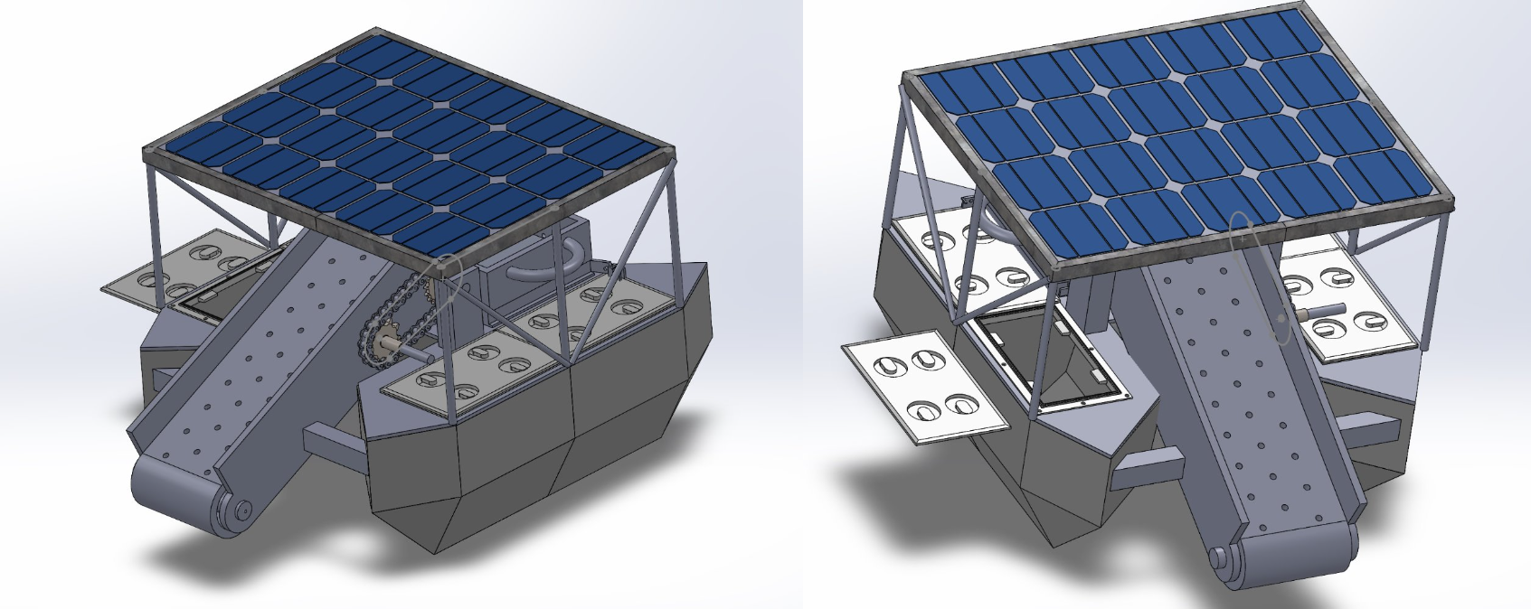
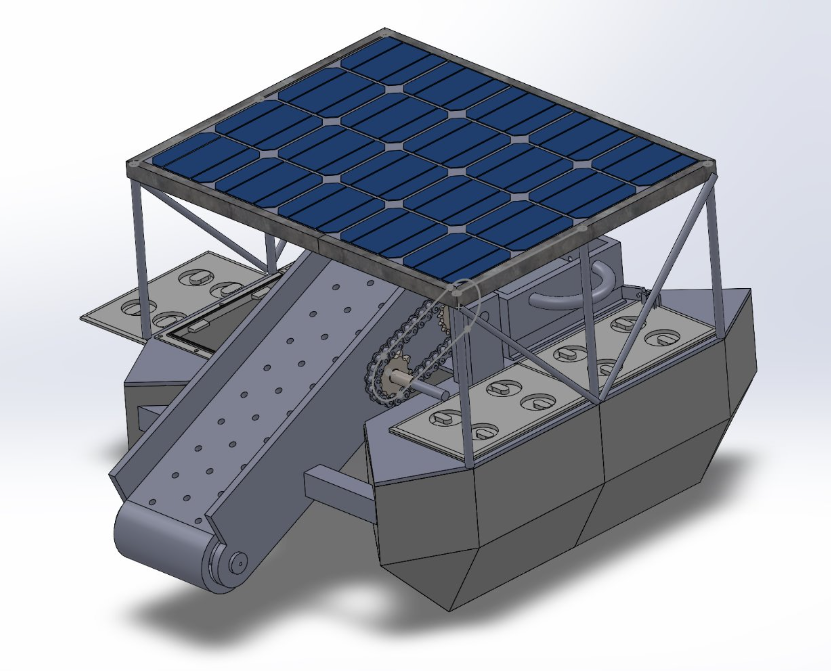
Using engineering calculations and CAD modelling, we developed and validated the final design of the RiverBin, a compact robotic skimmer designed to collect floating waste from local waterways before it reaches the ocean.
CONVEYOR BELT MECHANISM
Conveyor Load and Power Requirements
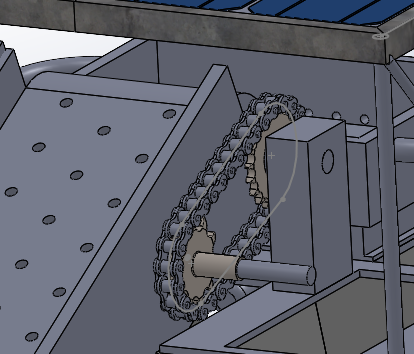
Transmission system
Motor
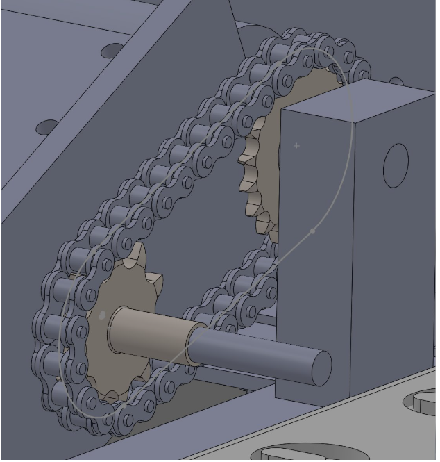
I analysed the stresses acting on the motor shaft caused by both torsion from the motor and radial forces from the chain drive. A safety factor was applied to account for rubbish impact and other dynamic loads giving a design force of 280 N acting on the sprocket system. Using bending moment and equivalent torque calculations, the maximum shear stress in the shaft was determined to be approximately 21 MPa, which is well below the allowable shear stress of 40 MPa for the material. This confirmed that a 15 mm diameter steel shaft was sufficient to safely transmit the required loads within the system.
Conveyor
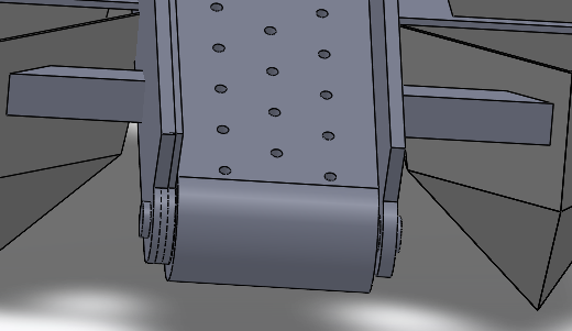
I analysed the conveyor drum shaft see if it could safely handle combined loading from the chain system and the conveyor belt/drum rubbish load. Using bending moment and equivalent torque calculations, I found the shaft shear stress remained well below the allowable limit. It was approximately 10.6 MPa for the sprocket-side loading case and 24.5 MPa under the combined belt/drum load case, both under the 40 MPa allowable shear stress.
I also designed and checked the shaft support brackets, modelling them as plate supports resisting bearing and bending stresses. The bracket bearing stress was calculated to be around 3.6 MPa, and bending stress around 20 MPa, which are both well below the material yield strength. Overall, this validated that a 15 mm shaft and mild steel support brackets provide a strong safety margin for real operating conditions.
DESIGN GOALS
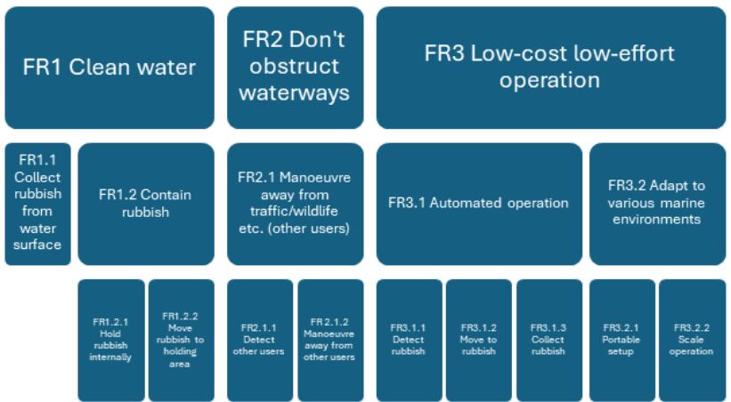
The functional requirements of the RiverBin were set directly from the needs identified during the problem analysis. The main requirements was for the system to effectively skim floating rubbish from the surface of the water, collect it using a conveyor mechanism, and store it for disposal at a station. Additionally the system needed to operate automatically or through manual control so users could target specific polluted areas while avoiding obstruction to other waterway users and wildlife. The design also aimed to be low-cost and easy to maintain so it could be used by smaller organisations or local communities. Several design constraints were also considered including the overall size and weight of the system, propulsion capability, and operational range and runtime in the water. These constraints ensured the skimmer remained practical, reliable, and suitable for deployment in small rivers, ponds, and harbours. From the image beside, it displays how the functional requirements were broke down to more easily identify the needs of the robot.
OVERALL DESIGN
In this project my main contribution was on the mechanical design of the conveyor belt system and supports. I designed the gear and chain drive system that transfers power from the motor to the conveyor drum. This included selecting an appropriate gear ratio to increase torque while maintaining a suitable conveyor speed for collecting floating debris. I also designed the support shafts for the conveyor belt working closely with my partner who was working on the conveyor belt design itself. Engineering calculations were performed to evaluate torque requirements, shaft stresses, and support loads to ensure the design remained within allowable material limits.
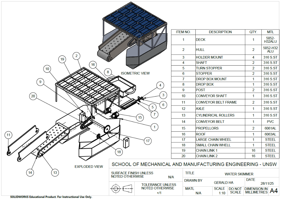
In addition to the mechanical design work, I created CAD models of the conveyor system and support structures to integrate the mechanism into the overall skimmer design. These models helped visualise the assembly and verify that the components would fit and function correctly within the system.
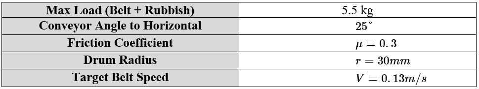
Firstly I used the specifications provided from my partner about the requirements for the conveyor belt which I had to use to analyse the forces on the conveyor drum and the torque needed to power the conveyor belt to the desired speed.
Force Analysis
Through force analysis, a 37.5 N of tangential force was required to move the conveyor. Using the drum radius, the torque required at the conveyor drum was calculated to be 1.13 Nm, and a safety factor of three was applied to account for operating conditions such as debris impact and friction losses. This resulted in a design torque of 3.39 Nm. From the target belt speed, the drum’s angular velocity and power requirements were determined, giving a required power of approximately 14.7 W. These calculations created the performance requirements needed to select an appropriate motor and transmission system for the conveyor mechanism.
To design the conveyor transmission system, I researched the different methods of transferring power from the motor to the conveyor drum. A chain and sprocket system was used because it provides reliable power transmission without slipping, which is important in wet environments. The final design uses a DC gear motor connected to a 10-tooth sprocket that drives a 20-tooth sprocket through a chain, creating a 2:1 gear ratio. This configuration reduces the rotational speed while increasing the torque delivered to the conveyor drum, allowing the belt to lift floating debris efficiently.
Shaft and Support design
Gear System
REFELCTION
Drum Support
From this project, it really opened my eyes to how theory applies to real life applications. Going through the process of problem to solution was much more complicated than anticipated however it was a very rewarding experience. Analysing real loading conditions, safety factors, and material limits gave me practice in real life engineering applications. It also highlighted how subsystem design must integrate with the overall system to produce a practical engineering solution. Some of the main takeaways from the project for me was ,
Mechanical power transmission design
Chain and sprocket transmission systems
Torque and power requirement calculations
Shaft stress and structural support analysis
Safety factor design for real-world loading
CAD modelling and subsystem assembly (SolidWorks)